With the release of FLAC3D 6, users were able to model zones and particles together for the first time. With PFC3D 6, Itasca has expanded these capabilities. Now you can work with discrete particles, clumps, and walls with finite-difference zones, interfaces, and structural elements all in one program. Imagine the possibilities! With PFC3D 6, and a valid FLAC3D 6 (or later) license, you can now load FLAC3D elements into the PFC3D environment. Built-in coupling capabilities take three forms.
Structural Element Coupling (1D)
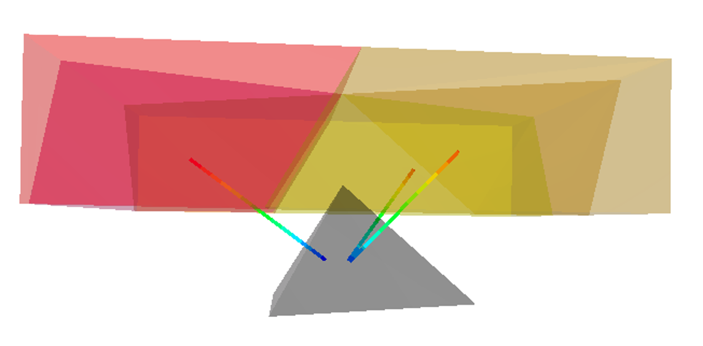
One-dimensional FLAC3D structural elements such as beams, cables, and piles can now be linked to PFC3D balls, clumps, and rigid blocks in a similar manner to zone links in FLAC3D.
Interface Coupling (2D)
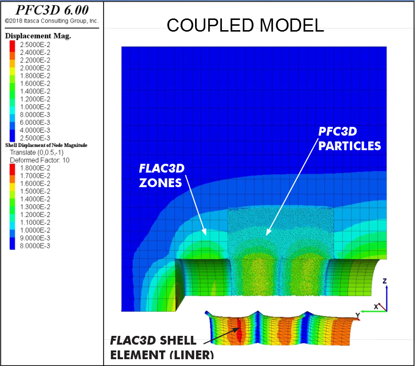
Couple PFC3D to zone faces and shell-based structural elements in pseudo-static simulations. PFC walls can be automatically created and slaved to FLAC3D zone faces or shell-based structural element faces. The motion of the wall vertices is slaved to that of the FLAC3D nodes, and forces exerted on the walls are transferred as externally applied forces (i.e., boundary conditions) to the FLAC3D nodes, resulting in an efficient two-way coupling. This functionality was first introduced in FLAC3D 6.
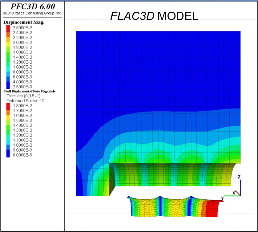
For example, below (left) is a staged-excavation tunnel model created and run in PFC3D 6 (left) that consists of FLAC3D zones and a portion of bonded particles. This is an elastic model. The bonded-particle micro-properties have been calibrated to match the mechanical properties of the FLAC3D zones (E = 40 MPa, v = 0.2). A smooth transition between the behavior of the zones and particles is clearly demonstrated. When comparing the coupled model (left) with the FLAC3D model (right), there is a good match between the response of two models. The tunnels in both models are lined with structural shell elements to represent ground support.
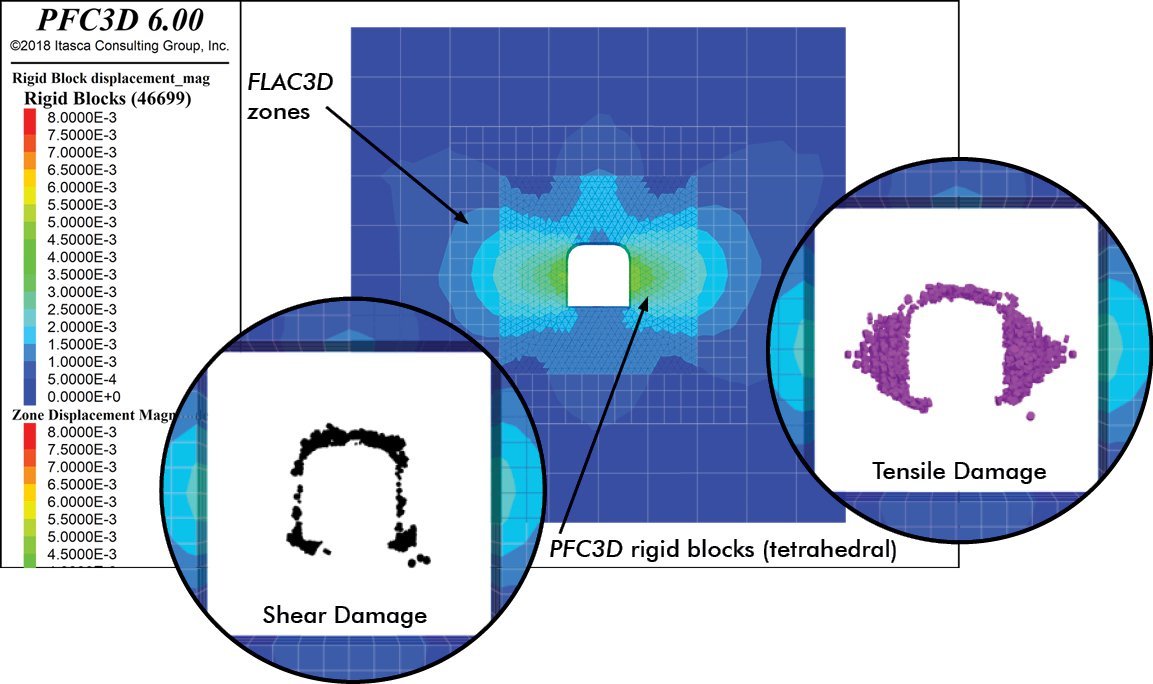
In another example, a model shows a tunnel excavated under highly anisotropic stress conditions (σH=3σV) using FLAC3D/PFC3D coupling to apply boundary conditions. Rigid blocks (tetrahedra) are used in the PFC3D region using periodic boundaries in the out-of-plane direction. Circular inserts show plots indicating the location of damage (black for shear failure and purple for tensile failure).
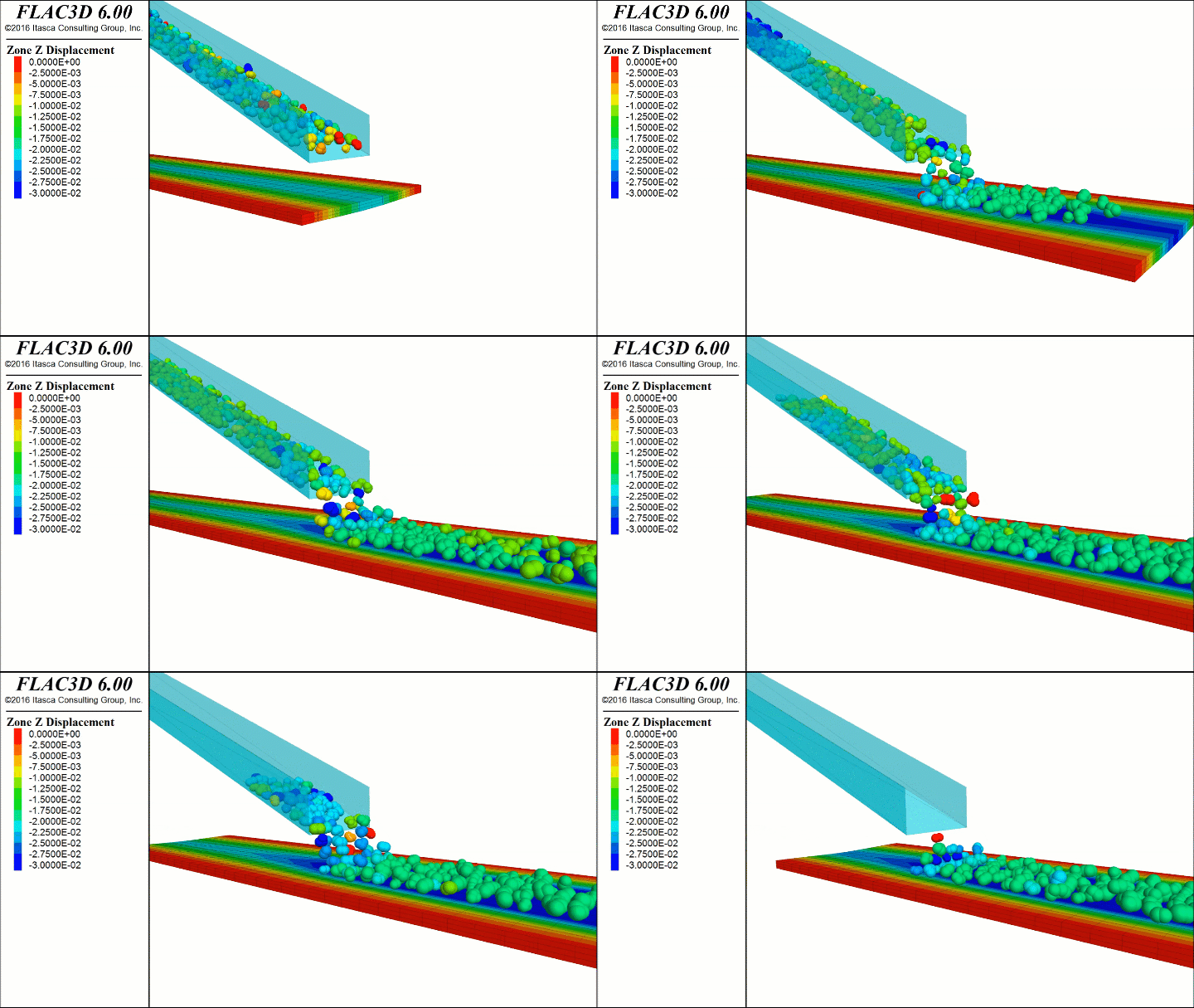
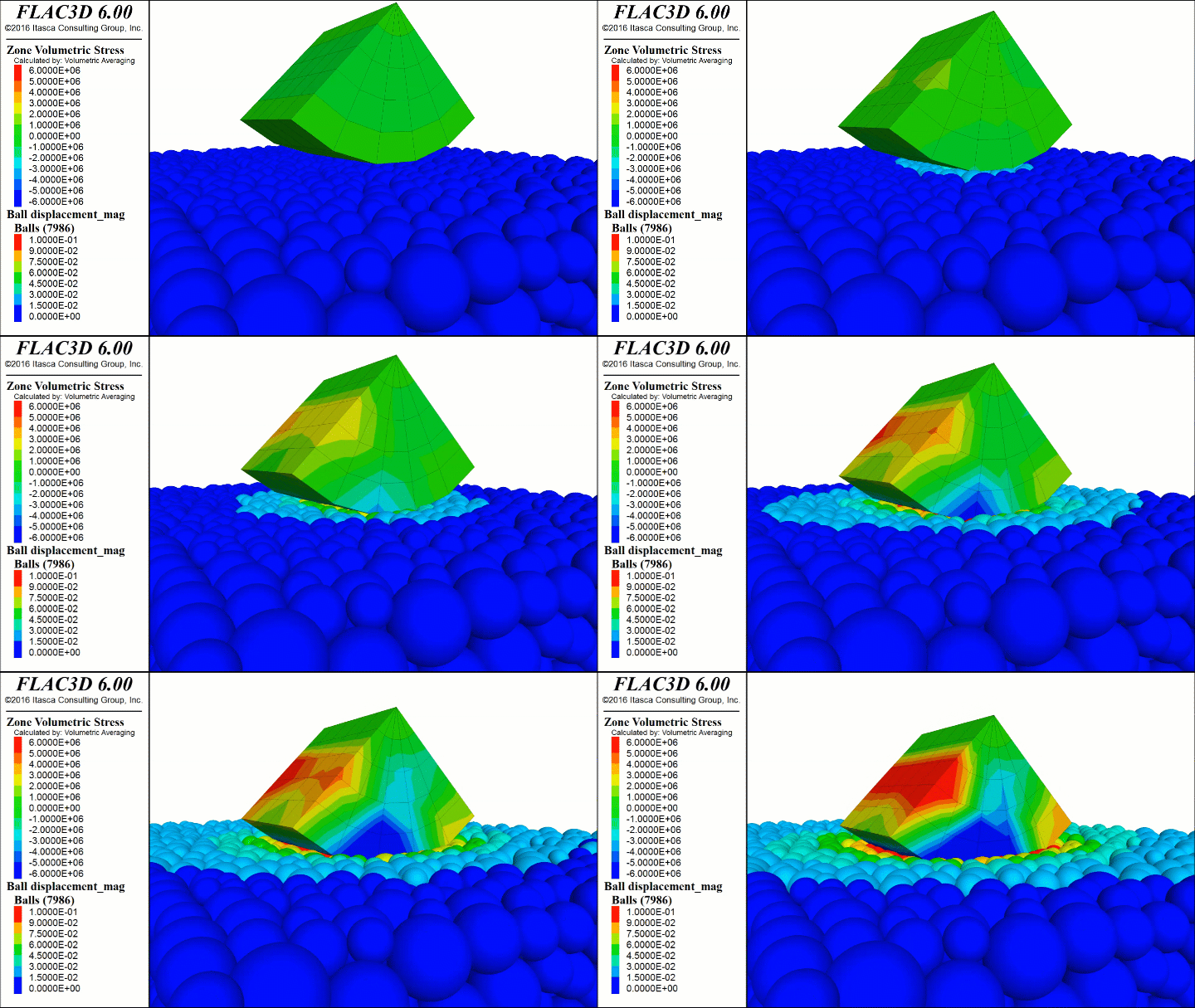
The following FLAC3D 6 examples are completely transferable to PFC3D 6. The first example (left) is a series of PFC particles are shown sliding down a chute onto a conveyor belt causing the belt to sag. The other example (right) is that of a punch made up of FLAC3D zones being pushed into another material consisting of bonded PFC3D particles.
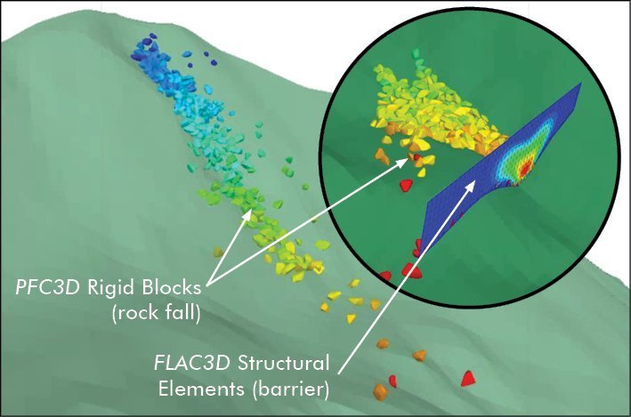
Another example of interface coupling is the use of 2D shell structural elements to represent protection nets in rock fall simulations. In the below figure, complex rigid blocks (not clumps) represent boulders moving down across a hillside represented by a wall topology. Towards the bottom of the hill, a barrier has been erected to impede any rock falls. Rigid blocks and the structural shell element are colored by displacement (color scales are different).
Domain Bridging (3D)
Couple PFC3D elements to FLAC3D zones. With this approach, the kinematics of PFC3D elements and FLAC3D zones is constrained within select regions of the model where they overlap to ensure displacement continuity.
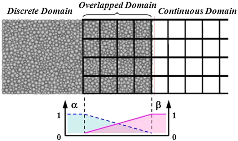
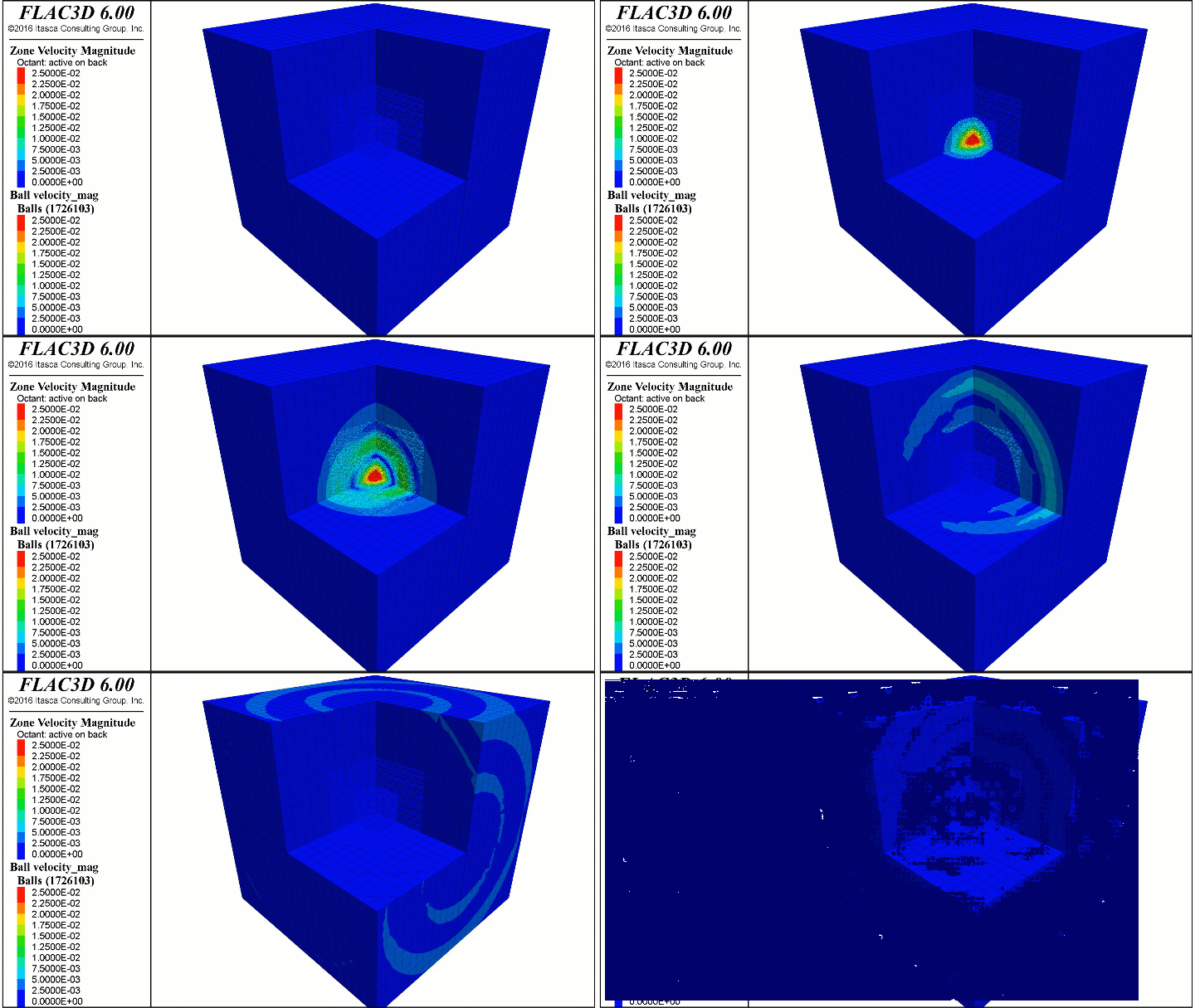
This approach can be used for quasi-static as well as for dynamic situations and minimizes spurious energy discontinuity between the different regions of the model. For example, the following dynamic wave propagation model employs an input ground motion (Ricker wavelet) applied to the center of the inner PFC3D model while ground motion displacements are recorded in the far field FLAC3D zones. The magnitude of velocity for both the particles and the zones are plotted below on a cutout of the balls and zones. The bridged model response agrees with the analytic solution from Stoke's Equation.
